Condition of assignment – Load Line Survey
.condition of assignment
.cap load line
Article link: https://marineengineeringonline.com/condition-of-assignment-load-line-survey/
These are the conditions which must be met before free board is assigned to a ship and load line certificate is issued following a load line survey. Free boards are computed assuming ship to be a completely enclosed and water tight / weather tight envelop. The convention then goes onto recognize the practical need for opening in the ship and prescribes means of protection and closure of such openings. These are called condition of assignment since the assignment of computed free board is conditional upon the prescribed means of protection and closure of openings such as hatchways, doorways, ventilation, air pipes, scuppers, etc. Following are the conditions which must be met before assigning the load line.
- Enough structural strength should be possessed.
- Enough reserve buoyancy should be possessed.
- Safety and protection of crew.
- Prevent entry of water through hull.
Ships to be surveyed annually to ensure that they fulfil the condition of assignment.
Most of the condition of assignment are concerned with the water tight integrity of the ship. Hull construction should meet the highest standard laid down by the classification society. This ensures protection against flooding of the ship. The superstructure and bulkheads must be strengthened sufficiently. Some of the condition of assignment which contribute towards water tight integrity are:
- Hatchways
- Machinery space openings
- Details of opening in free board
- Details of opening in superstructure deck
- Ventilators
- Cargo ports
- Air pipes
- Scuppers
- Side scuttles
- Inlet and discharges
All the above parameters ensure water tight integrity and protection against flooding of compartment. If above are not water tight then during rough weather water can enter into the areas below main deck causing to reduce the free board. So, condition of assignment very much contributes towards water integrity of the ship. Also, if green sea effect is not reduced and water is being accumulated on the deck, it can cause free board to reduce and add free surface effect. In rough weather if any longitudinal or transverse girder give way it can cause structural failure and water can enter area below main deck.
Because of this coaming, height of hatchways, height of sounding pipes and vent pipes are prescribed in M.S. load line rules.
Position 1 and Position 2 of Load Line
Load Line Positions
Load line positions refer to the locations of openings on a ship’s hull and superstructure in relation to the freeboard deck. These positions are crucial for determining the vessel’s watertight integrity and safety.
Position 1:
- Located on exposed freeboard and raised quarter decks
- Includes all openings in the freeboard deck
- Extends from the freeboard deck to 2.5% of the ship’s breadth or 500mm (whichever is greater) above the freeboard deck
Position 2:
- Located on exposed superstructure decks
- Includes all openings in the first tier of unenclosed superstructures
- Extends from Position 1 to 1 meter above Position 1
Here’s a simplified diagram illustrating Position 1 and Position 2:
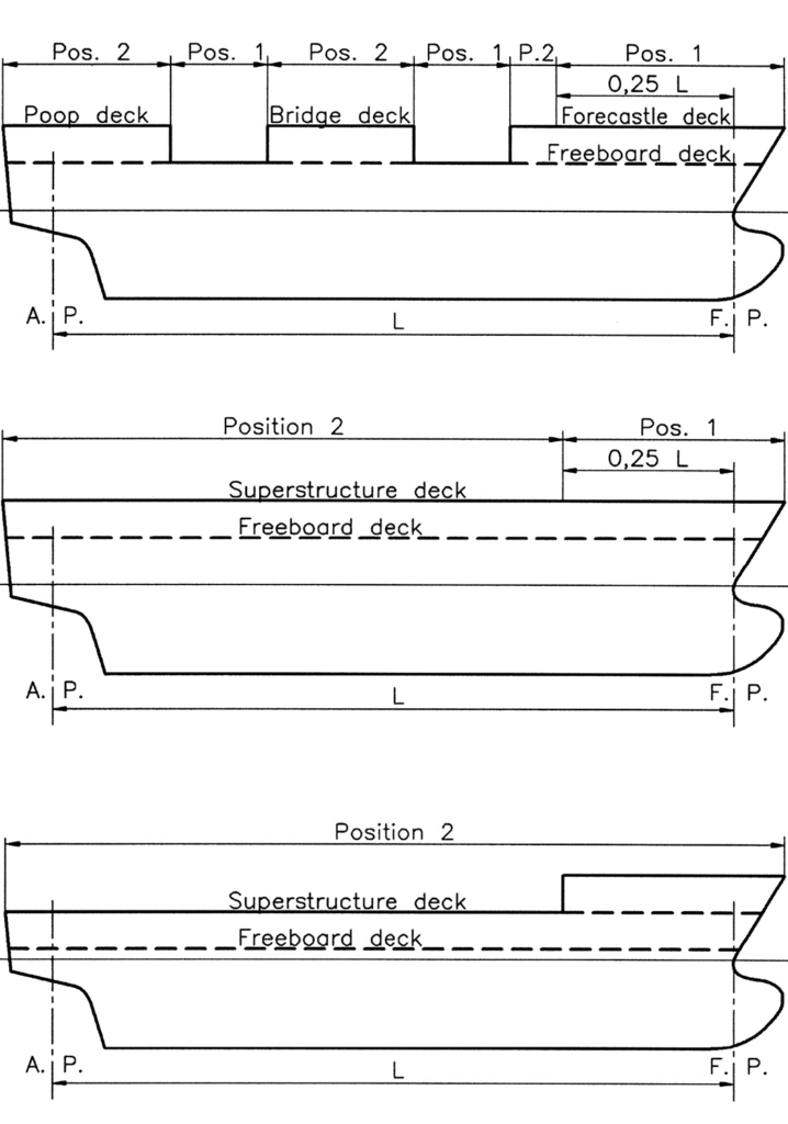
Diagram explanation:
The diagrams illustrate the concept of “Position 1” and “Position 2” as defined by the International Load Line Convention. These positions are crucial in determining the structural and safety requirements for different parts of a ship’s deck.
Explanation of Positions
- Position 1: This is the area of the ship that is more exposed to the sea. It includes the forward 25% of the ship’s length from the forward perpendicular (F.P.). In the diagrams, areas marked as Position 1 are typically at the bow of the ship, where they are more likely to encounter severe weather conditions. Structures and openings in this area must meet stricter weathertight and watertight requirements due to their exposure.
- Position 2: This area is less exposed compared to Position 1. It includes the remaining parts of the ship’s deck that are not within the forward 25% length. The requirements for weathertight and watertight integrity are less stringent here because these areas are more protected from direct exposure to the sea.
Diagram Details:
- Top Diagram:
- Shows a ship with multiple decks: Poop deck, Bridge deck, and Forecastle deck.
- Position 1 is marked at the bow, covering the forward 25% of the ship’s length.
- Position 2 covers the remaining areas, including parts of the Poop and Bridge decks.
- Middle Diagram:
- Illustrates a ship with a continuous superstructure deck.
- Position 1 is again at the bow, while Position 2 covers the rest of the deck.
- Bottom Diagram:
- Similar to the middle diagram but with a different superstructure configuration.
- Position 1 remains at the forward 25%, and Position 2 includes the rest of the superstructure deck.
Importance
These positions are critical for ensuring the ship’s safety and structural integrity. The Load Line Convention mandates that ships must have appropriate measures in place for these positions to maintain buoyancy and prevent water ingress, which is vital for the ship’s stability and safety at sea.